

By NAUE – The need to mitigate the impact of flooding has intensified as floods have become more frequent and serious. All types of dams are being reassessed. Their “impermeability” during emergencies, which is deeply connected to their integrity and overall safety, is of paramount importance. But how can these structures be monitored for better assurance of performance? NAUE was involved in a ground-breaking solution.
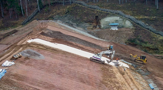
Monitoring pipes on the downstream face of the new Glashütte I dam indicate whether the impermeable barrier on the upstream face is functioning correctly. The hybrid design uses geosynthetic clay liners (GCLs) and geocomposites.
Not only has the design been unique, but its construction required a special “winter joint” to project the system during an early-onset winter that forced site work to be suspended for many months. Both the design and the winterizing protections have yielded valuable information for the geosynthetics and hydraulic engineering communities.
FLOOD DAM BACKGROUND
The Briesnitzbach River is a tributary of the Müglitz, which flows into the Elbe. The dam across the Briesnitzbach was previously only a few meters high. It was destroyed above Glashütte by extreme flooding in 2002. As an immediate measure, the small dam was rebuilt.
At the same time and location, the Saxon State Reservoir Administration (LTV) commissioned a new and much larger dam for the Glashütte I flood retention basin (FRB), which is below the Briesnitzbach dam.
The full construction work on the new FRB was completed in November 2013.
The 170m-long flood dam is designed to retain water, as needed, in order to control the flow into the Müglitz and the Elbe.
PIONEERING GEOSYNTHETIC APPLICATION
The Glashütte installation is important not only for flood control but for geosynthetics in general. It represents a remarkable application of these materials in dam structures. Although geosynthetics have been frequently and successfully used in hydraulic engineering for 40+ years, the general dam engineering field is not deeply aware of geosynthetics. The Glashütte project has provided an exemplary case for the beneficial impact of sealing systems on flood control and dam safety and performance.
Glashütte I is a “dry” or “green” retention basin. From the foundation of the flood dam seal to its crest, the dam is around 27m high. The basin holds up to 1 million m³. The upstream face is sloped at 1:2.5 with an intermediate berm approximately 9m below the crest. The downstream slope ranges from 1:2 to 1:2.8 and includes two berms to accommodate route K 9026. The dam was built as an earth-fill dam with an inclined inner seal. Up to a height of 16m, it has an impervious core of cohesive soil (k-value < 1 x 10⁻⁸m/s) of varying thicknesses, depending on the geometry.
DAM SEALING WITH BENTONITE AND DRAINAGE MONITORING
A composite system of geosynthetic clay liners (GCLs) sandwiching a central drainage composite protects the upper 11m.
This seal is built up as follows (from bottom to top):
- Embankment fill material (0/500mm) classified as GW, GI with U < 1.6 according to DIN 18196, with a compacted surface of fine subgrade material
- 3 – 5cm medium sand 0.2/0.63mm (support layer)
- Lower GCL: NAUE Bentofix® NSP 10300 a
- Drainage composite: NAUE Secudrain® 131 C WD 401 131 C
- Upper GCL: NAUE Bentofix® NSP 10300 a
- 60cm cover layer 0/32mm (sieved), of which 30 – 40cm was immediately applied on the day of placement
- Overlying embankment-fill material (see above) with topsoil cover and grass seeding
The drainage composite is part of the leak-detection system. Ideally, it should always remain dry. At its lower end, the seal feeds into a drainage prism filled with granular material 5.6/63mm and a drainage pipe.
At the side of the dam, the sloping drainage pipe connects to the downstream face of the dam by a solid-wall pipe installed at a gradient. The monitoring pipe penetrates the lower GCL. In a critical situation, the pipe shows whether the dam and its sealing system are holding.
When the basin is full, there should not be any water leakage.
The drainage prism is in the region of the bentonite seal, and is thus protected against water ingress from above and below by the two GCLs. The GCLs are brought together below the drainage prism and lead into the mineral sealing. The GCLs are set at a slope of 1:3. The transition to the upstream overall inclination of 1:2.5 has been made using the embankment-fill material.
The most important characteristics of the GCL (Bentofix® NSP 10300 a) are:
- Mass per unit area: 10.410g/m² of which:
- Substrate (PP woven) 110g/m²
- Bentonite (Na Bentonite) 10kg/m²
- Upper layer (PP nonwoven) 300g/m²
- kf value: 2 x 10-11m/s
- Permittivity: < 5 x 10⁻⁹ 1/s
- Thickness: 9mm
Thus, the specified materials fulfill the design requirements, in particular the weight of bentonite (> 9kg) and the permittivity (< 5 x 10⁻⁹ 1/s).
It is worth mentioning that GCLs here use only high-quality sodium bentonite. This grade of bentonite would even have met the required permittivity with only 5kg of bentonite and a layer thickness of 6mm. Nevertheless, the tender was awarded with 10kg of bentonite—a strong factor of safety and still economical for the project.
A total of 12,000m² of Bentofix® GCL and 6,000m² Secudrain® geocomposite were installed.
PROTECTION OF INSTALLATION JOINTS
The installation of the approximately 6,000m² of verifiable seal started in the second week of November 2012, but by the end of the month the installation had to be interrupted due to the early onset of what turned out to be a long winter. The edges of the GCL were covered with a geomembrane to protect them from the weather. This “winter joint” strategy (wrapping the edges in geomembrane) and the sufficiently thick cover material atop the GCLs ensured the integrity of the material until the spring.
Construction resumed in late April 2013 and, shortly thereafter, the sealing system was completed.
Due to the sensitivity of the site and the innovative design, a specialized technical installation company was retained for the work. Quality assurance (QA) was given the highest priority.
All work involving geosynthetics was carried out according to landfill-construction QA specifications, which are the most stringent available. The client appointed an accredited office/laboratory not only for overall construction but for site supervision, external testing, and the suitability testing of the specialist installation company.
External site testing was demonstrated on all operations involving geosynthetics. Installation was performed strictly in accordance with the geosynthetic manufacturer’s instructions, which are also part of the positive assessment of the GCLs by the LAGA. QA paid particular attention to the winter joint. Sampling and laboratory testing verified the integrity of the GCL at the winter joint.
As noted earlier, geosynthetics have not been as deeply utilized in dam engineering applications as they have in other sectors of infrastructure. Frictional stability of the proposed geosynthetic system was investigated prior to the Glashütte site’s approval, both as part of due diligence and to better familiarize the dam engineering stakeholders with geosynthetic quality and performance.
The Institute of Geotechnical Engineering at Leibniz University of Hanover conducted several experiments with a large direct shear box. They tested the internal shear strength of the GCLs and all “joints” (or interfaces) between:
- GCL (bottom) and sand layer
- GCL (top and bottom) and drainage composite
- GCL (top) and the capping layer
The testing confirmed suitability, and the use of a verifiable seal on the dam enabled not only a modern design but a highly efficient one.
It is anticipated that this design will make a truly beneficial contribution to improving the understanding of geosynthetics in hydraulic engineering. It will provide a strong precedent for adapting these construction materials and methods into similar flood dam sites going forward for better flood control and flood system safety.
The professional implementation by the construction company (STRABAG AG, NL Dippoldiswalde/Dresden) and the specialist installer for GCLs (ENIG GmbH, Arnstadt)—in spite of partially adverse weather conditions—a flood retention basin has been created which will be groundbreaking for similar projects worldwide due to its progressive design and economical structure.
For more dam engineering and geosynthetics information, and for additional case studies and resources regarding other sectors of engineering, visit www.naue.com.


