
Lightweight Foamed Concrete (LWFC) is being investigated by the Railway Engineering Research Institute (RERI) in China as a potential subgrade foundation at bridge transition zones. It has the characteristics of low density, high stiffness, easy access to material that is convenient to construct. Here, Geosynthetica presents the paper “Study on Mechanical Properties of 35T-40T Heavy Haul Railway Lightweight Foamed Concrete Subgrade,” which comes from the GAP 2019 transportation conference proceedings (published by Geosynthetica). Authors Li Tai-feng, Chen Feng, Li Zhong-Guo, Stephen Wilk, and Colin Basye report on indoor mechanical test, full-scale model test, and an in-situ construction test at Transportation Technology Center, Inc. (TTCI).
1. INTRODUCTION TO LIGHTWEIGHT FOAMED CONCRETE SUBGRADE
Subgrade, as a geotechnical structure, due to its simple and reliable structure, convenient construction and wide selection of filling materials (ZHANG Q.L. et al. 2008, ZHANG Q.L. et al. 2016), which has been widely used in railway construction. Compared with the general axle load trains, the subgrade for the heavy haul railway will face two technical problems. First, the increase of axle load will cause the increase of subgrade load, and the superposition effect of subgrade internal stress will be obvious, which required more strength and transmission depth to maintain the stability and workability of the subgrade. Second, the operation of long marshalling trains will increase the number of continuous action of subgrade, which will make it difficult for the accumulated pore pressure in the subgrade soil to dissipate in time, cause the reduction of the effective stress and the strength of the subgrade (YE Y.S et al. 2012, ZHANG W.T 2017). In addition, the design life of China’s heavy-haul railway subgrade is generally 100 years, the requirements of subgrade durability and structural form rationality become much stricter.
The use of LWFC subgrade can effectively solve the problem of difficult compaction and differential settlement in the transition section (CHEN Z.P. et al. 2004), since the LWFC has the characteristics of low density, well stiffness, and convenient construction. In order to comprehensively understanding the structural characteristics of LWFC heavy-haul railway subgrade (YANG C.F. et al. 2016), this paper will focus on the study of the stress-strain relationship and the dynamic response of LWFC subgrade structure under the action of 35t-40t axle load by using in-door mechanics test, full-scale dynamic test and in-situ construction test.
2. INDOOR MECHANICAL TEST OF LWFC
2.1 Fundamental characteristics of LWFC
LWFC is a kind of light material which made from the aqueous solution foaming agent, mixed and stirred with cement-based cementitious material and optional aggregate in a certain proportion (M.R. Jones. et al. 2005), which has the characteristics of adjustable density, light weight and simple construction. Therefore, the LWFC has been widely and successfully used in both railway and highway engineering construction. In this test the water-cement ratio of LWFC specimen is 0.5, the wet density is between 400kg/m3 to 1000kg/m3, and the regression curve of the LWFC compressive strength (28d) is obtained and shown in Figure 1.
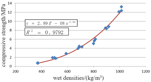
It can be seen from Figure 1, there is a well correlation between the compressive strength and the wet density of lightweight foamed concrete. The correlation coefficient of the regression curve R2=0.9792, which indicates that the compressive strength of LWFC is largely dependent on the wet density. The 28d compressive strength of LWFC (600 Kg/m³ in wet density) is greater than 2MPa, which basically meet the requirements of subgrade filling material. By the consideration of both reliability and serviceability, the LWFC with wet density as 800 Kg/m³ are recommended to be used for the subgrade of heavy haul railway. In order to give LWFC a certain universality, the relationship between the relative strength and the relative density has been obtained and shown in Figure 2 and the relationship can be written as Eq.(1):
 (1)
(1)
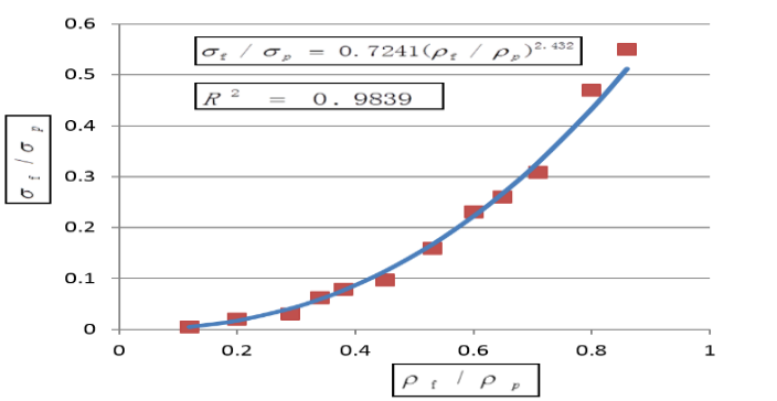
Where is the strength of LWFC, is the strength of the slurry, is the wet density of the LWFC, is the density of the slurry.
Figure 2 shows that the strength of the LWFC is proportional to the strength of the slurry. The relative strength in the Eq.(1) is expressed as the strength of the LWFC divided by the strength of the slurry, this can minimize and eliminate the effect of differences in slurry strength. According to the Eq.(1), the strength of the LWFC under any wet density can be calculated, when the mixture ratio, strength and density of the slurry are known. Moreover, the strength of LWFC can be adjusted according to the Eq.(1) to the same density, when the density of the LWFC produced by different batches are different.
RELATED: Geosynthetics in Diverse Railroad Applications
2.2 Compressive strength test
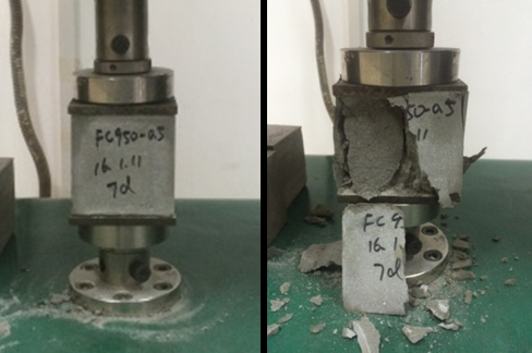
Figure 3 shows the compressive strength test of the LWFC. The wet density of LWFC specimen is 800kg/m3 with geometry size as 100mm*100mm*100mm. The external load was continuously and uniformly applied to the test specimen until the specimen was close to failure. Recorded the failure load when the specimen was destroyed. The test process is showed in Figure 3.
The compressive strength of the concrete cube should be calculated accurately to 0.01mpa with Eq.(2):
![]() (2)
(2)
Where is the compressive strength of concrete cube specimen (MPa), F is the failure load of specimen (N), A is the pressure area of the specimen (mm²).
In order to satisfy the requirements of both Chinese National Design Code and Technical Code of Cast-In-Situ LWFC for Heavy-Haul Railway Construction, the compressive strength of the LWFC specimen should be measured and satisfied the standard requirements after curing for 7d and 28d respectively. In this test, the compressive strength of LWFC at 7d has been measured as 1.55 MPa, which is greater than 0.8 MPa, and the compressive strength of LWFC at 28d was 2.63 MPa which is greater than 1.5 MPa.
2.3 Freeze-thaw cycle test
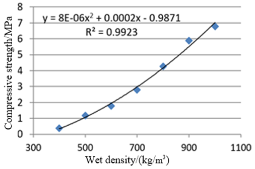
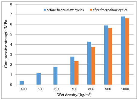
Specimen with different wet densities were prepared in this laboratory freeze-thaw cycle test. The size of specimen was 100mm*100mm*100mm, with the wet density between 400kg/m3 to 1000kg/m3. After curing for 28 days, the unconfined compressive strength test was conducted at first. Then the compressive strength has been measured after 25 freeze-thaw cycles, shown in Figure 4. As the wet density increases, the compressive strength of the lightweight foamed concrete gradually increases. When the wet density changes from 400kg/m3 to 1000kg/m3, the compressive strength increases from 0.37MPa to 6.79MPa.
The compressive strength loss of LWFC with different wet density before and after 25 freeze-thaw cycles is shown in the Figure 5. The maximum loss rate of compressive strength is 15% for the specimen with wet density of 800kg/m3. The maximum loss rate of compressive strength of 900kg/m3 and 1000kg/m3 after 25 freeze-thaw cycles is 4%. The 400kg/m3~600kg/m3 specimen has a large mass loss after 15 freeze-thaw cycles, hence it is impossible to carry out the compressive strength test. Therefore, the wet density of the LWFC should be greater than 800kg/m3 to ensure the strength and the serviceability of LWFC subgrade can maintain in a well acceptable status.
2.4 Dry-wet cycle test
The influence of moisture on the strength and other mechanical properties of LWFC is obvious. In practical engineering, LWFC is greatly affected by the dry-wet cycle. With the same specimen density and size as freeze-thaw cycle test. Again, the unconfined 28d compressive strength should be checked firstly. Then, the compressive strength was measured after 25 dry-wet cycles (WANG L.J. et al. 2017).
Figure 6 shows the loss of compressive strength of LWFC after 25 dry-wet cycles with different wet densities. According to the Figure 6, the maximum compressive strength loss of LWFC after 25 dry-wet cycles was about 15%, which is reasonable and acceptable for the design requirements. Therefore, LWFC has strong resistance to the dry-wet cycle. The overall physical properties and durability of the LWFC with a wet density of 800kg/m3 can be safely used as a subgrade filling material for heavy haul railway.

3. FULL-SCALE MODEL TEST OF LWFC
3.1 Test objective
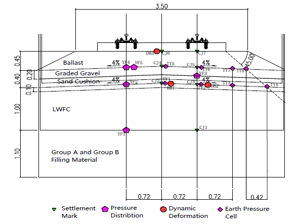
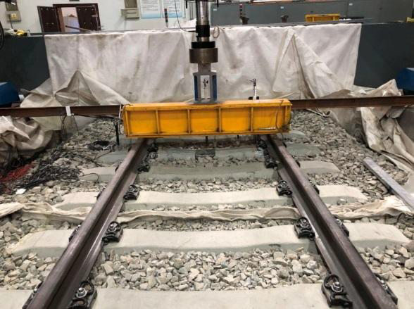
This full-scale model test will mainly focus on the dynamic response characteristics and pressure distribution of LWFC subgrade structure under the action of 35t-40t dynamic load. Figure 7 shows the LWFC subgrade structure for the full-scale test which used for the heavy-haul railway. The thickness of LWFC was 1m in this test, which replace partial bottom layer of original subgrade. The ballast of 0.45m thick is overlaid on the graded gravel layer (0.2m). Then 0.2m sand cushion layer (with composite geomembrane) has been laid which can improve the overall permeability properties of LWFC subgrade structure (FENG W. et al. 2015, LV W.Q. et al. 2016). In order to simulate the train dynamic load in this LWFC subgrade structure full-scale model test. The mega pulse fatigue test machine would be used to add the dynamic load on the rail track (Figure 8).
3.2 Test program
In order to test the dynamic deformation resistance and mechanical stability of LWFC subgrade structure, the settlement observation marks with Linear Variable Differential Transformer (LVDT), the dynamic pressure cells and the pressure distribution sensors and will be used. The layout of all the dynamic sensors is shown in Figure 7. The basic parameters of the lightweight foamed concrete subgrade structure are shown in Table 1.
Table 1. The basic parameters of LWFC subgrade structure
| Subgrade layer | Density (g/cm3) | EVD (MPa) |
| LWFC | 800 | 152 |
| Graded gravel | 2.1 | 44.7 |
The maximum dynamic test force of the mage pulse fatigue test machine is 500kN, and the frequency of dynamic load is 5Hz. The geometric size of the model test tank is 6.8m*5m*3.3m. In order to determine the stability and reliability of the LWFC subgrade structure, the dynamic stress with 30t, 35t, 40t, 45t axle load was applied to the test structure respectively (under natural drying conditions). Then, both 35t and 40t axle loads with 2 million times were applied to the LWFC subgrade structure under the water immersion condition respectively, which verify the mechanical stability and impermeability of the structure. The loading scheme of full-scale model test is shown in Table 2.
Table 2. The loading scheme of full-scale model test
| Water immersion situation | Loading level /kN | Loading cycles /ten thousand times |
| Naturally dry | 300 | 200 |
| 350 | 200 | |
| 400 | 360 | |
| 450 | 80 | |
| Fully immersion | 350 | 200 |
| 400 | 200 |
3.3 Pressure distribution in vertical direction
Figure 9(a) and Figure 9(b) show the vertical pressure pf each layer under the 30t-40t axle load condition. It can be seen that the vertical pressure of each layer presents a linear rule with the increase of external load. Under the same load condition, the vertical pressures are highly depends on the depth and the position of the point. The vertical pressure at the same location decreases by 35% with the depth increases by 0.4m, under the dynamic load of 350kN. Moreover, the vertical pressure decreases by 30% with the depth increases by 0.4m under the 400kN dynamic load.

3.4 Deformation status of dynamic load test
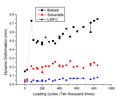
Figure 10 shows the dynamic deformation at the surface of ballast, graded gravel and LWFC under the condition of 300kN-450kN dynamic load. It can be seen that the overall dynamic deformation of LWFC is less than 0.1mm, which is relatively low. The LWFC subgrade has reasonably well dynamic stability under the dynamic load of 450kN.
RELATED: Permanent Deformation and Stiffness of Fouled Ballast
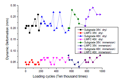
Figure 11 shows the dynamic deformation at the surface of both graded gravel and LWFC, under the condition of naturally dry and fully immersion. It shown that the LWFC subgrade has well stable mechanical properties and well serviceability performance, since the overall dynamic deformation is less than 0.075mm.
4. IN-SITU CONSTRUCTION TEST OF LWFC
4.1 Test objective
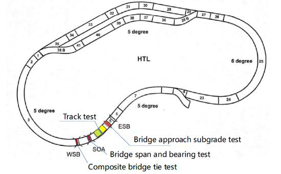
The LWFC has the characteristics of low density and convenient construction. It can be used as a transition section structure to effectively solve the problem of partially compaction. The site for this project is located at the High Tonnage Loop (HTL), at the west approach of the East Steel Bridge (ESB), shown in Figure 12.
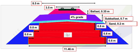
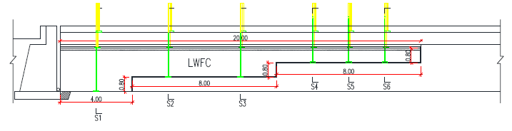
The transition section is divided into three steps with a height change of 0.8m. The thinnest part of lightweight concrete should be no less than 0.8m. Metal mesh is set 0.1m away from the top surface of the LWFC. Deformation joints with a width of 2cm and 0.2m depth will be made at each step. The whole structure of the LWFC subgrade is completely wrapped with HDPE film, and the sand cushion is laid on the top surface of the LWFC. The wet density of LWFC should be controlled around 800 kg/m3, the 7days compressive strength should be greater than 0.8MPa and the 28days compressive strength should be greater than 1.5MPa. The transverse-section and the vertical-section of LWFC subgrade structure have been shown in Figure 13 and Figure 14.

4.2 Test content
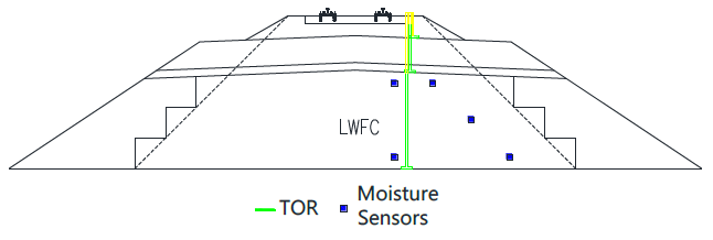
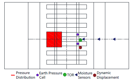
The main test contents of this test include earth pressure test, dynamic deformation test and moisture content test. The surface cracks and erosion status of LWFC should be observed and measured before and after the test. The deformation of LWFC subgrade and the differential settlement of transition section should be measured for each 10MGT. The sensors arrangement have been detailed shown from Figure 15 to Figure 18.
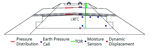
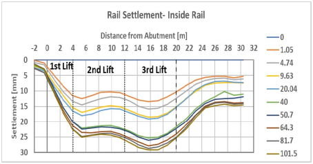
4.3 Track Settlement
The test vehicle consists of three locomotives and 110 carriages, each weighing 35.4 tons. The maximum operation speed is 64 km/h and the accumulated driving weight for each night is about 2 MGT. Figure 19 shows the settlement and deformation of the track structure (rail) along the longitudinal direction, the overall settlement of test section tends to be stable with no significant increase after 40MGT (101.5 MGT has been completed so far). Starting from the initial settlement of track structure: the total settlement of track (rail) is 28mm (after 100 MGT), and the settlement of subballast is about 9.5mm. Figure 20 shows the average stratified settlement of each layer after passing the weight of 100MGT, in which the compressive deformation of LWFC subgrade layer is about 4.6mm. Overall, the performance was well and in accord with expectations.

4.4 Dynamic Testing and Results
4.4.1 Earth pressure
Figure 21 and Figure 22 show the test results of the earth pressure cells in section 2 and section 5, wherein the average surface pressure of LWFC is basically stable at about 60kPa, and the surface pressure of graded gravel is about 110-140kpa, which is related to the driving speed and axle load, hence the service performance is basically well.


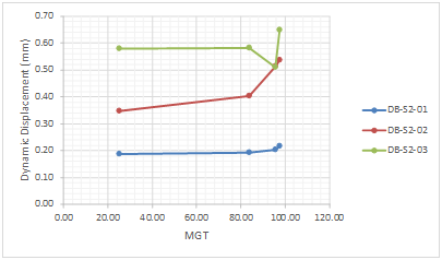
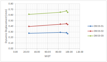
4.4.2 Dynamic displacement
Figure 23 and Figure 24 show the dynamic displacement test of section 2 and section 5, in which the dynamic displacement of graded gravel surface is about 0.6mm, and the dynamic displacement of LWFC surface is about 0.4mm. Since the position of section 2 has two steps, where the dynamic displacement is smaller than that of section 5 (single step).
4.4.3 Moisture
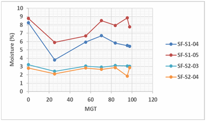
Figure 25 and Figure 26 show that the water content on the surface of LWFC increases slightly compared with that on the bottom, and the water content in section 1 is slightly larger than that in section 2, but there is no obvious abnormality, and the overall performance is basically stable.

5. CONCLUSIONS
Lightweight foamed concrete has stable mechanical properties with relatively light weight and small compressive deformation, which is suitable for construction of special railway subgrade section and bridge transition section, where the deformation requirements are strict. It can effectively reduce the differential settlement between different structures and provide sufficient bearing capacity.
For the LWFC with a wet density of 800kg/m3, the laboratory test results show that it has high compressive strength and well mechanical stability, which can be used for the new design of heavy-haul subgrade structure.
The structure of LWFC subgrade has well impermeability and water stability, which can avoid the subgrade diseases caused by the influence of water. The results show that the overall dynamic deformation of LWFC under the fully immersion condition is still less than 0.075mm, which indicates that the structure of the LWFC subgrade has relatively high stability to resist deformation and excellent serviceability performance for the dynamic load.
The lightweight foamed concrete bridge transition section structure with wet density of 800kg/m3 is designed and tested with in-situ construction test. The results shown that the LWFC subgrade has reasonably well workability and stability to resistant the heavy axle load, the structure can also reduce the differential settlement of bridge transition section and redistributed the stress uniformly.
ABOUT THE AUTHORS
Li Tai-feng, Chen Feng, and Li Zhong-Guo are with the Railway Engineering Research Institute, China Academy of Railway Sciences Corporation Limited. Stephen Wilk and Colin Basye are with the Transportation Technology Center, Inc.
ACKNOWLEDGMENTS
This work is funded by the Science and Technology Research and Development Plan of China Railway Corporation (2015G004-C, J2017Z505) and the Foundation of China Academy of Railway Sciences Co., Ltd.(2016YJ039, 2017YJ044, 2018YJ030).
REFERENCES
CHEN Z.P. & WANG S.L. & DENG J. 2004. Foamed mixture lightweight soil. Beijing: China Communications Press: 1-32.
FENG W. & LEI X.T. & WANG X.Q. 2015. Experimental study on mechanical property of cast-in-situ foamed light soil. Urban Roads Bridges & Flood Control 2015(05): 205-207.
LV W.Q. & LUO Q. & LIU G. et al. 2016. Structural analysis and design method for subgrade bed of heavy haul railway. Journal of the China Railway Society 2016(38): 74-81.
M.R. Jones, A. McCarthy 2005. Preliminary views on the potential of foam concrete as a structural material, Magazine of Concrete Research. 57 (1): 21–31.
WANG L.J. & YE Y.S. & ZHANG Q.L. et al. 2017. Experimental study on behavior of foamed light soil in water immersion. Railway Engineering (1): 103-106.
YANG C.F. & ZHUANG C. & LI H.L. et al. 2016. Analysis on stress-strain relationship of foamed lightweight soil in widening of freeway on soft soil foundation. Journal of Guangxi University (Natural Science Edition) 41(01): 234-245.
YE Y.S. & ZHANG Q.L. & SHI C.L. et al. Study on key technologies of heavy haul railway subgrade under 30t axle load. 2012. Beijing: China Academy of Railway Sciences: 41-56.
ZHANG Q.L. & CAI D.G. & MA W.B. et al. Study on the structure design method and parameters of railway subgrade bed. 2008. Beijing: China Academy of Railway Sciences: 14-21.
ZHANG Q.L. & LI Z.G. & CHEN F. et al. Study on road performance and control parameters of lightweight materials for railway subgrade. 2016. Beijing: China Academy of Railway Sciences: 127-133.
ZHANG W.T. 2017. Discussion on subgrade widening settlement deformation control and monitoring of high-speed railway. Railway Standard Design 61(04): 47-50.


