By John Sankey and Robert Lozano – For discrete reinforcing strips used in MSE walls, standards developed under the AASHTO codes have identified a method for evaluating pullout of ribbed steel reinforcements through conservative default values using a friction factor term identified as f*. A similar default basis for polymeric reinforcing strips is not available in AASHTO; only values meant for geotextiles and geogrids. But how do we characterize high tenacity polymeric strips? What follows is a summary of research that will be presented during GeoMontreal 2013, September 29 – October 3.
MSE Design
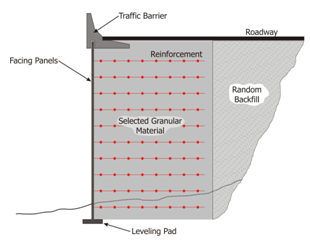
The basis for MSE walls is centered on the combination of facing, reinforcements and backfill acting as a coherent mass to form a retaining wall structure (Figure 1). Design is typically divided between considerations for internal and external stability. Internal stability addresses the pullout resistance and tensile capacity of reinforcements used in the MSE wall. External stability addresses sliding and overturning of the MSE volume, as well as means to determine settlement, bearing and global stability of the retaining structure.
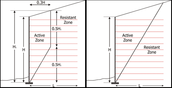
When focusing on internal stability and its relationship to pullout resistance, it is necessary to divide the reinforced volume into active and resistant zones (Figure 2). AASHTO classifies reinforcements under two broad categories of inextensible (commonly identified with steel reinforcements) and extensible (commonly identified with geosynthetic reinforcements). In either category, the pullout resistance is only considered in the portion of the reinforcement found in the corresponding resistant zone. The pullout resistance itself is based on the frictional stress transfer between soil and reinforcement.
Current Polymeric Strip Reinforcement and Testing Program
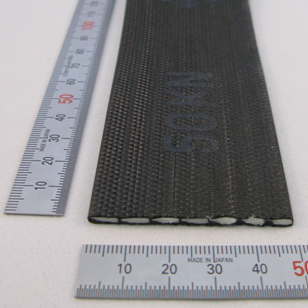
Generally speaking, the pullout behavior of polymeric strip reinforcements is independent of the strength; rather it is highly dependent on the surface dimensions, type of surficial treatment of the sheath and to some extent the volumetric amount of LLDPE used in the sheath. The data presented here is focused on strips of approximately 50mm width with a nominal tensile strength of 50kN
A testing program for characterization of pullout behavior of a 50 mm strip was performed using ASTM D6706 – Standard Test Method for Measuring Geosynthetic Pullout Resistance in Soil. The standard has been used extensively for evaluation of pullout capacity of all types of reinforcements used in MSE structures including steel.
The pullout testing equipment used is a custom made pullout box with plan dimensions of 0.60 m by 1.50 m and an overall depth of slightly over 300 mm. Normal loading was applied using six hydraulic cylinders, while pullout loads were applied to the test specimen through a harness connected to hydraulic rams.
Since the pullout length of polymeric strips is critical to correctly model the values of f*, the length of specimen was limited between 1220 to 1320 mm.
The state of the practice for geosynthetic reinforcements typically uses only three normal loads to determine pullout characteristics of a material with resulting outputs taken at the peak coefficient of interaction of the material.
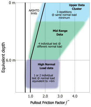
To provide sufficient data in regards to polymeric strips, a minimum of five normal loads should be considered, one exceeding the equivalent overburden of 6.0 meters and the other loads evenly distributed at equivalent depths from near surface to 6.0 meters.
Conclusions from Testing
- Polymeric strip pullout behavior has similar characteristics to the pullout behavior of ribbed steel strips, though f* trends are somewhat less for the polymeric strip.
- The authors’ methodology is applicable for any pullout testing targeting f*. It is important to include an established statistical analysis on the general trends of the data, particularly for low confinement stresses.
- While AASHTO does not provide any guidance on f* behavior of polymeric strips, the current data available for 50 mm wide strip should be sufficient to predict pullout behavior in sand.
- Further research is needed for coarser soils such gravel and will be the source of future research.
- Testing with sufficient repetitions is considered good practice to reduce intrinsic problems with precision and bias, resulting in an accurate prediction of the pullout behavior.
- There is sufficient indication that pullout behavior under submerged conditions is different from moist conditions. Further testing will be needed to investigate the differences more thoroughly.
For full discussion of the testing parameters, data, and related design considerations, visit with the authors at GeoMontreal 2013.
Acknowledgements
The authors will like to recognize and thanks to Zehong Yuan (SGI Testing services), Linda Nait-Ali and Yassine Bennani (Terre Armée – SoilTech) for their help in the preparation of this paper.
John Sankey and Robert Lozano work for The Reinforced Earth Company, Reston, Virginia, USA. www.reinforcedearth.com


